
Jul 20,2026
Pageview: 99
Every seasoned electrical technician has a story about the one that got away. A perfectly functional VFD drive, an expensive HVAC controller, or a home automation panel that failed overnight after a mild thunderstorm. The post-mortem often points to an overvoltage protector that quietly degraded, losing its ability to clamp transients without showing any visible sign of failure. Your multimeter, the most accessible weapon in your diagnostic arsenal, can uncover these silent failures—if you know what to look for. This guide details how to systematically test these protective components and, when you discover a failed unit, introduces a monitoring approach that upgrade to a real-time monitoring protection device prevents this kind of unplanned downtime altogether.
Before we touch any meter leads, a hard safety rule applies: overvoltage protectors, especially those wired into AC circuits, can hold a dangerous capacitive charge long after power is removed. Always verify zero potential with a non-contact voltage tester, then manually discharge any capacitor banks across the line. The few seconds this takes is cheap insurance against a jolt that can destroy your meter or worse.
Start with your eyes. A healthy metal oxide varistor (MOV) should be smooth, shiny, and uniform in color. Look for these telltale signs of death:
Cracks or pinholes on the epoxy coating, suggesting thermal stress.
Darkened or charred body — this indicates a catastrophic short circuit event.
Fractured leads or melted solder joints caused by excessive current.
Even if the MOV passes a visual check, it can still be electrically open or degraded. That’s where your multimeter comes in.
An MOV is the workhorse inside most plug-in surge strips and industrial protectors. Its job: hold high resistance at normal voltage, then abruptly drop resistance to shunt transients to ground.
Set your DMM to the resistance mode (Ω) and select the highest range, typically 20 MΩ or auto-range.
Isolate the MOV from the circuit completely. In-circuit testing often gives false readings due to parallel paths.
Place the probes across the MOV terminals. A healthy MOV should read open circuit or several megaohms. A reading of less than 1 kΩ indicates a shorted, failed device. A completely open reading might be normal, but it could also mean the MOV failed open during a past surge. Use the next step to differentiate.
Switch to diode test mode. Some meters can apply enough voltage to observe a slight junction reading on a good MOV, but more importantly, any low or steady conduction in one direction suggests a breakdown. For precise clamping voltage validation, a specialized component tester with a higher voltage source is needed, but for field go/no-go checks, resistance and visual cues cover 90% of failures.
GDTs are often found in telecom equipment and high-speed data lines. They appear as small ceramic cylinders, sometimes with metal end caps.
Resistance test: A functional GDT should read completely open (infinite resistance) across its terminals. Even a few megaohms indicates internal contamination or insulation breakdown. Replace it.
Breakdown verification (the faint-glow check): If your multimeter has an insulation resistance testing function (megohmmeter) that outputs 250V or 500V, you can check if the GDT fires. Connect the GDT across the meter, ramp up the voltage, and watch for a sudden drop to a low glowing voltage (typically 90-150V for a 230V GDT). Never use this method on installed wiring without disconnecting sensitive electronics downstream.
Transient Voltage Suppression diodes protect sensitive DC circuits. Test them exactly like a normal silicon diode but with an understanding of their unidirectional or bidirectional nature.
For a unidirectional TVS: You should measure a forward voltage drop of around 0.6V to 0.7V in one direction and open circuit in the reverse direction. Any reading below 0.4V in both directions means it’s shorted.
For a bidirectional TVS: You should read open circuit in both directions using standard diode test mode. A short in either polarity means failure.
Mistake 1: Measuring without isolating the component. You test an MOV while it’s still across the line and L-N terminals, and the meter reads continuity. You condemn the protector, only to realize later you were reading the transformer primary winding. Always lift at least one lead.
Mistake 2: Using continuity mode for everything. A beep test is almost useless for surge protectors. Most MOVs and GDTs are high-impedance devices; they should never make your meter beep. Continuity mode is for finding short circuits, not validating overvoltage protection.
Mistake 3: Ignoring age. MOVs degrade incrementally with each surge event. A protector that absorbed twenty small transients over five years might still read “open” but its clamping voltage has drifted dangerously upward, leaving your equipment exposed. This accumulated fatigue is invisible to a basic resistance check.
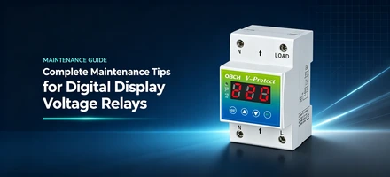
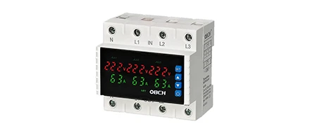
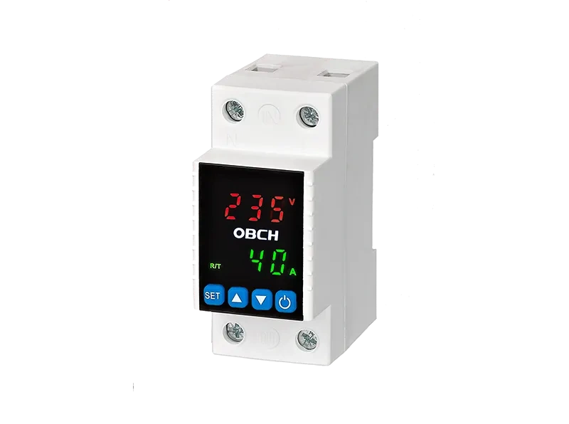
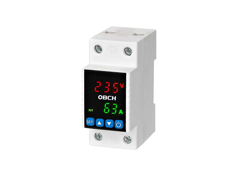
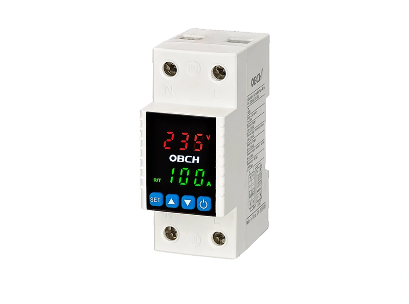
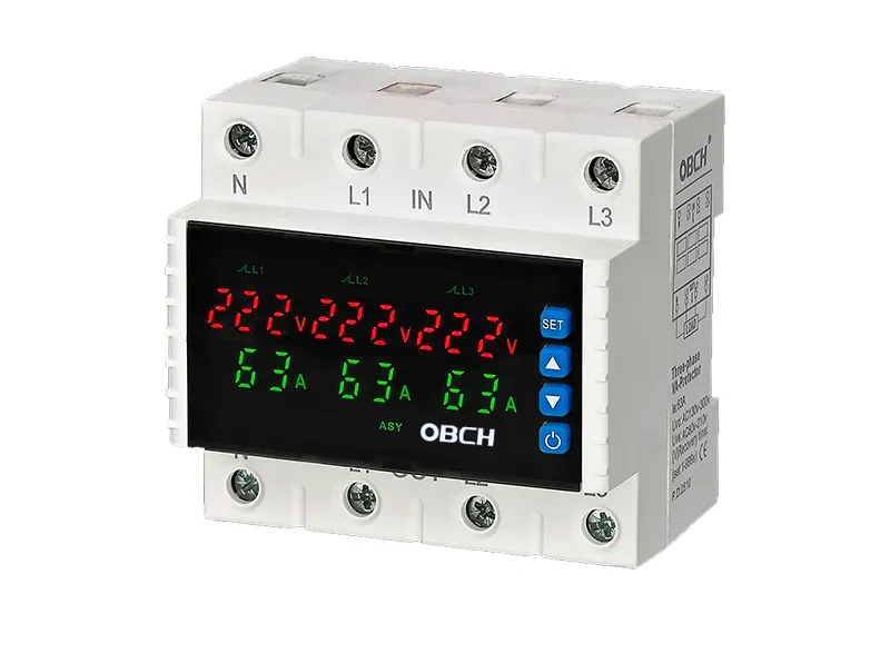
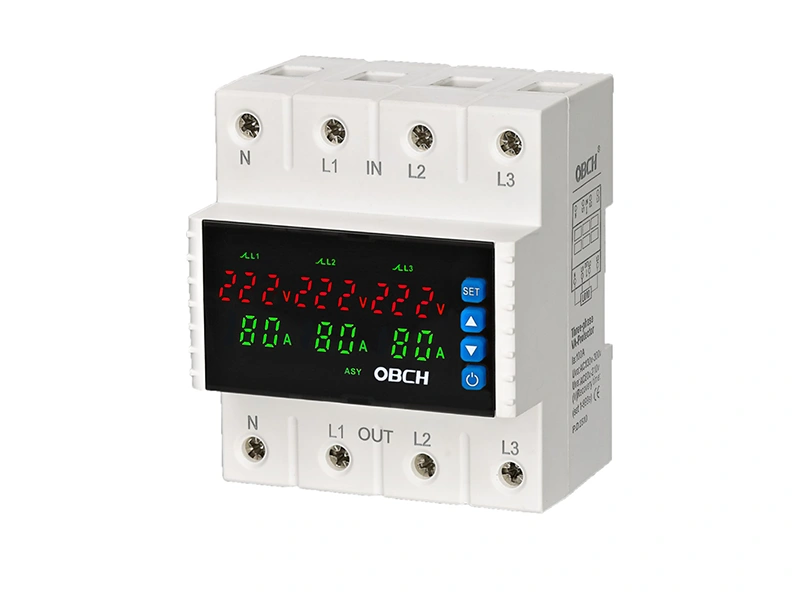
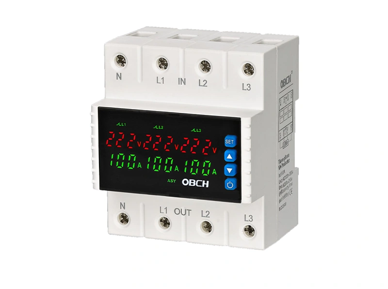
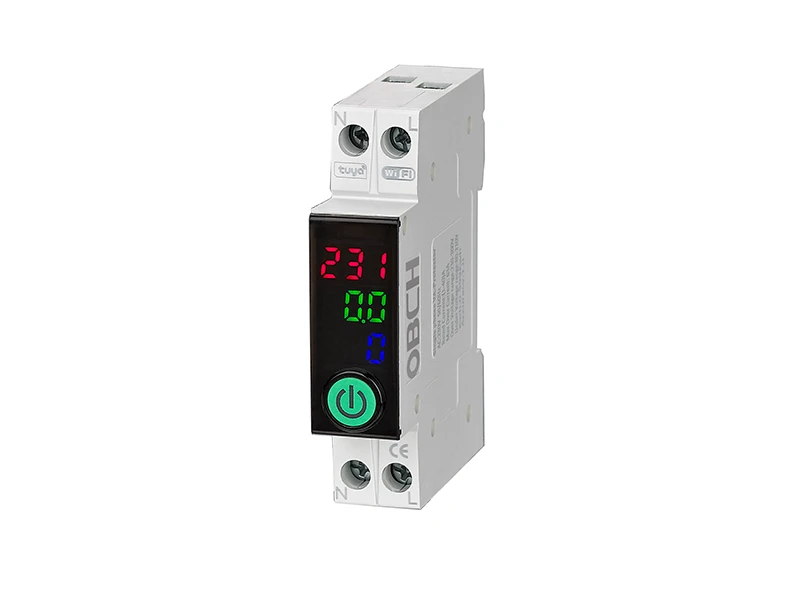
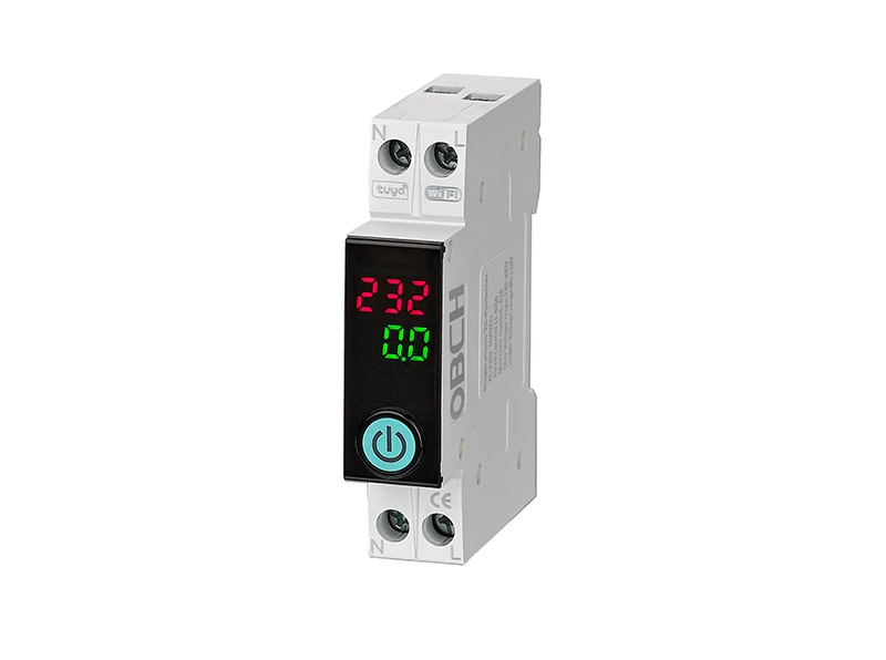
If your test confirms a failed protector, you could simply solder in an identical component. But in environments where equipment uptime is revenue-critical, this reactive approach leaves a gap: you still don’t know when the next degradation begins. A modern voltage current protector with an integrated digital display turns this opaque safety layer into a transparent, predictable system. By continuously showing real-time voltage, load current, and surge event counters, it lets you install a complete protection unit with live diagnostics rather than waiting for the next smoky breakdown.
Instead of annual physical checks with a multimeter, you get immediate visibility into protector health. Internal logging captures the number of surges absorbed, so you can schedule replacement based on actual stress, not a calendar guess. This is especially valuable for remote installations like pumping stations or telecom huts where on-site visits are expensive. The diagnostic data justifies the hardware swap to management with hard numbers, not hunches.
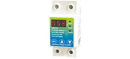
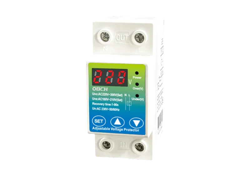
When a failed overvoltage protector is discovered on a critical branch circuit—say, powering a CNC controller or a server rack—there is genuine peace of mind in installing a solution that actively watches the line. Obch’s voltage current protector is built precisely for this use case. It offers adjustable over/under-voltage thresholds, a clear LCD readout of electrical parameters, and a relay output that isolates the load before damage occurs. The device records fault history so you can analyze whether issues stem from grid instability or internal load spikes. Explore Obch’s smart safety solutions and their full specifications.
In the end, a multimeter test is an excellent triage tool, but it is still a snapshot. Pairing that skill with continuous monitoring transforms your electrical protection from a sacrificial component into an informed guardian. The next time a storm rolls through, you won't just hope the protector held—you’ll know.
Disclaimer: Testing overvoltage protection components involves working with potentially hazardous voltages. Always follow local electrical codes, use appropriate personal protective equipment, and consult a licensed electrician if you are uncertain about any procedure.

 English
 Chinese
 Pусский
 Français
 Español
 Deutsch
 Português
 한국인
한국인 عربي
عربي