
Jul 27,2026
Pageview: 72
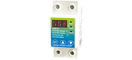
When selecting an adjustable voltage protector, the decision should not be based on price or brand alone. The most critical factors are the voltage adjustment range, protection accuracy, available protection functions, and whether the unit provides clear status indication. This guide breaks down the key specifications you need to evaluate, what trade-offs to consider, and the questions to ask before making a choice. By the end, you will have a practical framework to compare options and match a protector to your actual electrical environment.
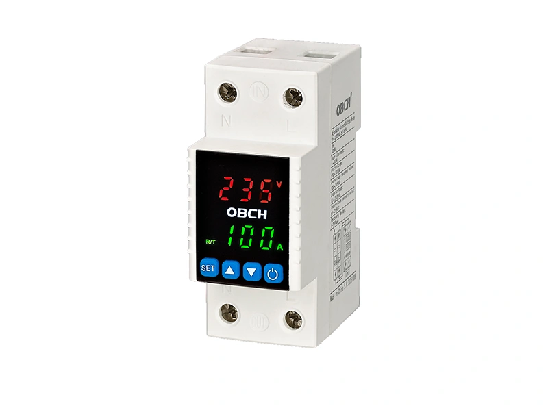
The adjustable voltage range determines both the under‑voltage and over‑voltage thresholds you can set. A wider range offers more flexibility, but it is only useful if your application experiences real voltage fluctuations near those extremes.
What to examine:
Lower limit (under‑voltage): Should be set high enough to protect equipment from brownouts, but not so high that normal grid variations cause nuisance tripping.
Upper limit (over‑voltage): Must be above your normal maximum operating voltage, yet low enough to disconnect before sensitive components are damaged.
Hysteresis / reset window: The difference between trip and reconnection voltage. Too narrow, and the protector may cycle on and off frequently; too wide, and your equipment may remain off longer than necessary.
A protector that allows independent adjustment of under‑voltage and over‑voltage set points offers better control in unstable grids. If your site experiences simultaneous under‑voltage and over‑voltage events, look for a unit that can monitor and react to both in a coordinated way.
Action: Before browsing configurations, record your normal operating voltage range and the maximum deviation your equipment can tolerate. This information will help you directly compare the specifications in the adjustable voltage protector category.
A basic voltage protector only disconnects on under‑voltage or over‑voltage. More advanced units integrate additional protection features that can prevent multiple types of electrical faults.
Functions to evaluate:
| Protection Feature | What It Does | When It Is Important |
|---|---|---|
| Over‑current protection | Trips when current exceeds a set limit | Motor loads, equipment with inrush currents |
| Time delay on restart | Waits before reconnecting after a trip | Compressor‑based equipment, refrigeration |
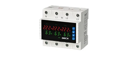
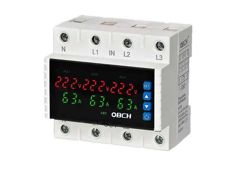
| Phase loss detection | Disconnects if one phase fails | Three‑phase equipment, industrial motors |
| Surge / transient suppression | Absorbs short‑duration voltage spikes | Areas with frequent switching or lightning exposure |
| Automatic reset | Restores power once voltage normalizes | Unattended installations, remote equipment |
Not every application needs all functions. A simple under/over voltage relay may suffice for a residential‑grade appliance, whereas an industrial pump set may require phase loss protection and a configurable restart delay. Prioritize functions based on the actual failure modes that could damage your connected load.
If you are uncertain which protection combination fits your equipment profile, reviewing the technical specifications available through the adjustable protector product page can help you identify models with the specific functions your system demands.
Adjustment accuracy—how closely the actual trip point matches the set point—affects the real‑world protection level. Two values matter:
Setting resolution: The smallest step change you can make (e.g., 1 V or 0.1 V).
Trip accuracy: The maximum deviation between the set value and the measured trip voltage under varying temperature and load conditions.
In sensitive applications, such as laboratory instruments or precision manufacturing, a deviation of even a few volts can be problematic. For general commercial loads, standard accuracy may be sufficient. Always check whether the manufacturer states the accuracy under specific operating conditions (ambient temperature range, load type, and supply voltage stability). If accuracy data is not available, confirm with the supplier whether the stated protection thresholds are factory‑calibrated and whether field recalibration is possible.
The user interface determines how easily you can set parameters and diagnose events. There are two common approaches:
Digital display with real‑time readings:
Shows actual voltage, current, and sometimes fault codes.
Enables precise digital setting via buttons, reducing setting errors.
Allows immediate verification of current grid conditions without additional meters.
Potentiometer or dial adjustment without display:
Generally lower cost.
May be harder to set accurately, especially in poorly lit panels.
Often lacks stored fault memory, making post‑event troubleshooting difficult.
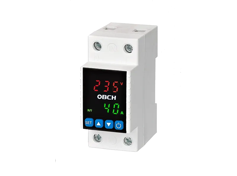
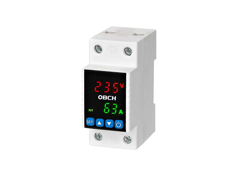
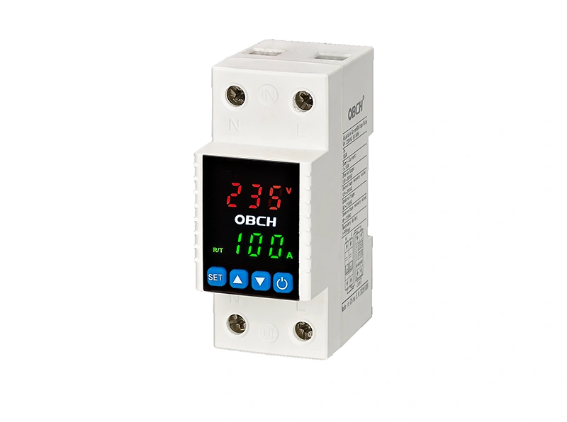
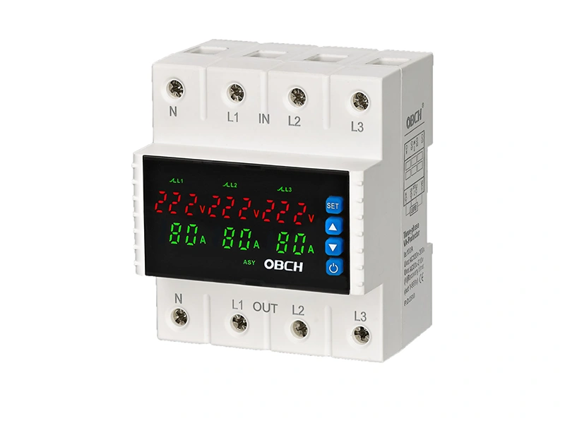
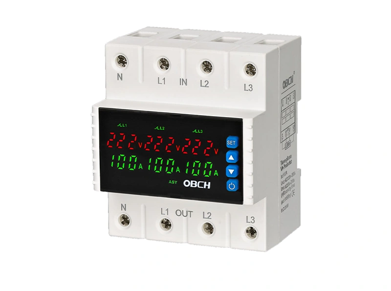
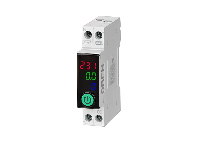
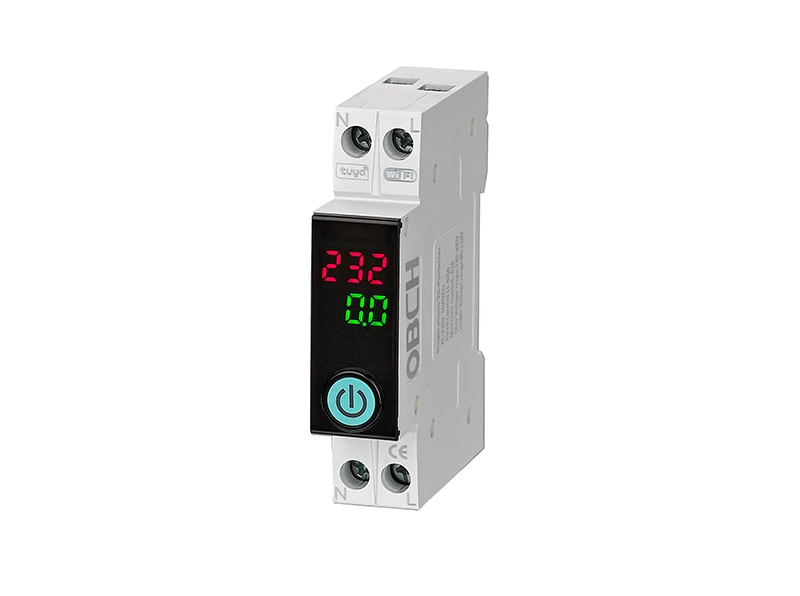
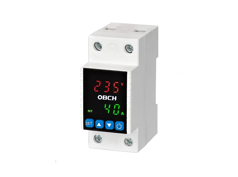
For installations where multiple people may interact with the protector, or where recording fault history is valuable, a digital unit with a readable display is the more practical choice. As an example, a model like the OBS7‑6‑VA1PN digital voltage/current protector with a lighting logo integrates a digital interface for at‑a‑glance status confirmation and simplified parameter entry. When comparing options, consider whether a digital interface will reduce setup time and improve fault diagnosis in your specific environment.
The nature of the connected load influences which protector characteristics matter most:
Resistive loads (heaters, incandescent lighting): Straightforward protection. Over‑current limits are predictable.
Inductive loads (motors, transformers, solenoids): Inrush currents can be several times the rated running current. The protector must distinguish between a genuine fault and a momentary inrush, usually through a short intentional delay or an inrush‑tolerant response curve.
Capacitive loads (power supplies, LED drivers): High switch‑on surges and harmonic currents may cause nuisance tripping if the protector is not designed to tolerate brief capacitive charging.
Mixed loads: The most challenging. You may need to segment the circuit or select a protector that allows per‑channel adjustment or has configurable trip delays.
If your equipment has a nameplate that shows rated current and locked‑rotor current, bring those values when comparing the current handling capabilities of different adjustable protectors.
The installation environment imposes practical constraints:
Panel‑mounted vs. DIN‑rail: Confirm the mounting method matches your panel layout. Most industrial protectors use DIN‑rail mounting for quick installation.
Ambient temperature: High panel temperatures can derate the protector’s current handling capacity. Check whether the rated current is valid at your expected operating temperature.
Humidity and dust: If the panel is in a non‑conditioned space, a protector with a conformally coated PCB or an appropriate IP rating may be necessary.
Supply voltage fluctuations: In areas with extreme grid instability, the protector’s own power supply must work reliably over a wide input voltage range. Otherwise, the protector itself may become a reliability risk.
Documenting these installation‑side conditions will help you filter unsuitable models quickly and focus on the options that are mechanically and electrically compatible.
A protector is a safety device; its reliability must be verifiable. Before finalizing a selection, ask:
Does the unit have a manual test function to simulate an over‑voltage or under‑voltage trip?
Is there a self‑diagnostic routine that checks internal components on power‑up?
How is the internal relay rated? (AC‑1, AC‑3, or AC‑15) – this determines the electrical life under inductive loads.
What is the expected electrical endurance (number of switching cycles at rated load)?
Are replacement or repair services available if the unit fails after installation?
Without published endurance data, a common industry expectation is that a quality relay‑based protector should comfortably handle tens of thousands of operations under typical conditions, but actual service life depends heavily on load type and switching frequency. Whenever possible, conduct an on‑site test with a representative load before deploying large numbers of units across a facility.
Use this checklist when comparing adjustable voltage protectors:
Q: What is the difference between a fixed voltage protector and an adjustable one?
A: A fixed protector has pre‑set trip thresholds that cannot be changed. An adjustable unit lets you define the exact under‑voltage and over‑voltage limits, which is essential when protecting equipment with a narrow acceptable voltage window or when operating in areas with varying nominal voltage.
Q: How do I determine the correct under‑voltage setting?
A: Identify the minimum operating voltage specified by your equipment manufacturer. Add a small safety margin (typically 5–10 V depending on the voltage level) to avoid nuisance trips caused by transient dips that the equipment can still handle.
Q: Does a digital display improve protection performance?
A: The display itself does not change the trip accuracy, but it reduces setting errors, provides real‑time grid diagnostics, and helps record fault events—all of which improve the overall reliability of your protection scheme.
Q: Can one adjustable voltage protector cover both single‑phase and three‑phase systems?
A: It depends on the model. Some protectors are designed specifically for single‑phase, others for three‑phase, and a few can handle both with appropriate configuration. Always check the manufacturer’s specification for the number of phases supported.
Q: What is the expected lifetime of an adjustable voltage protector?
A: Lifetime varies by relay quality, load type, and switching frequency. Under typical service with properly rated loads, a quality protector may operate reliably for many years. Ask the supplier for endurance test data based on your specific load profile.
Q: Should I choose a protector with automatic reset or manual reset?
A: Automatic reset is convenient for unattended equipment that is safe to restart without inspection. Manual reset is safer for equipment where an unexpected restart could create a hazard. Some units allow you to select the reset mode according to your preference.
Choosing the right adjustable voltage protector starts with a clear definition of your operating voltage envelope and the protection functions your load truly needs. Prioritize models that give you independent control over under‑voltage and over‑voltage set points, deliver accuracy commensurate with your equipment sensitivity, and offer an interface that minimizes setup errors. Avoid the trap of selecting the most feature‑rich unit without verifying that each function serves a genuine purpose in your electrical environment.
Once you have settled on your technical requirements, the next step is to compare actual product configurations and identify models that match your checklist. You can begin by exploring the adjustable voltage protector options available at OBCH’s adjustable voltage protector section, where you will find detailed specifications and configuration possibilities.

 English
 Chinese
 Pусский
 Français
 Español
 Deutsch
 Português
 한국인
한국인 عربي
عربي